
Anatomy of a Junction: One
The King’s Scholars’ Pond Sewer: St. John’s Wood
When a fellow underground aficionado first ventured into a London sewer his planned journey began in St. John’s Wood, in an unremarkable section of the King’s Scholars’ Pond Sewer (K.S.P.S.). Unremarkable as it was the 5.5ft x 3.5ft egg shaped sewer bombarded John with curious new sights, sounds and smells. He later remarked “There is a fatal fascination about sewers, and whenever an entrance is opened, a crowd is sure to gather . .” (Hollingshead, John. Underground London. 1862).
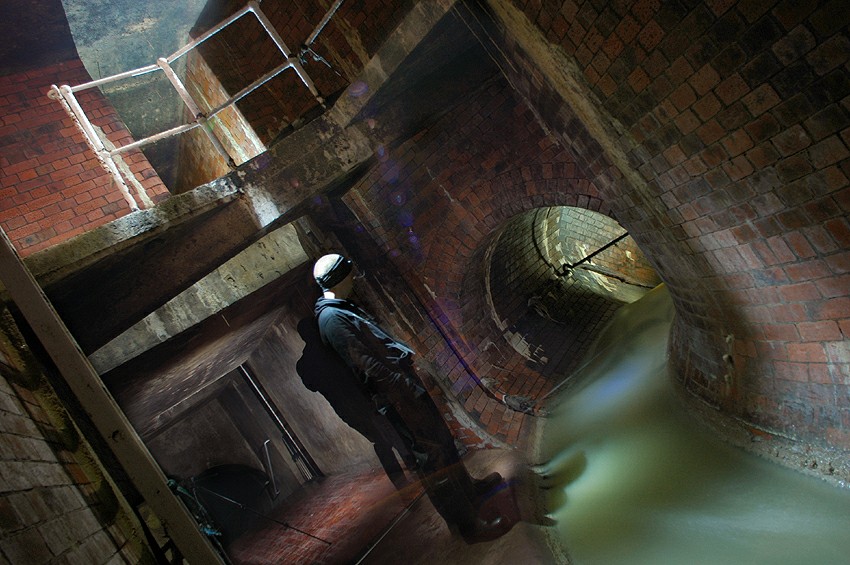
Pic. 1 – The junction as seen in 2010, looking downstream to the inspection gallery.
The same section of tunnel where John Hollingshead began his virgin sewer expedition in 1860 has seen considerable alteration over the past 150 years; in 2010 there’s certainly more to remark upon, and more so to bombard the senses. This short text goes some way to unravelling a complex and compact sewer junction. The K.S.P.S. runs for approx. five miles in a south-easterly direction from Hampstead to the Thames. Located within the most northerly portion of this five mile run, the section we’re looking at did not receive any attention during the groundbreaking overhaul of London’s Main Drainage, under Joseph Bazalgette, Chief Engineer of the Metropolitan Board of Works. For an eighty five year period, from it’s construction c.1825 (Fig.1) to the construction of the London County Council’s Middle Level Sewer No.2 (Fig.2) in 1910, it remained unaltered. The timing of Hollingshead’s visit did in fact mean he travelled the entire route of the K.S.P.S. prior to any of Bazalgette’s major alteration works.

Fig. 1 – The original sewer tunnel pre alterations.

Fig. 2 – 1910 interceptor works creating the first phase of the junction.
The connection to the MID LVL SWR No.2 was the first stage of works forming the basis of the junction as it appears today. This first junction was a relatively simple set up where dam boards were installed in the K.S.P.S. tunnel immediately downstream of a new connection which diverted the sewage flow into a circular brick pipe measuring 5.6ft in diameter. The diversion pipe dropped the flow down a series of steps (Tumbling bay) to the intercepting sewer passing beneath the K.S.P.S., as seen in Fig.2.

Fig. 3 – 1940s Penstock works.

Fig. 4 – 1980s works, being the last to date.
A further thirty years passed with no works in the immediate vicinity of the junction, then in 1940 a penstock chamber was built on the downstream side of the dam boards. This allowed the K.S.P.S. tunnel to be entirely sealed off no matter what the volume of flow, diverting all its content into the intercepting sewer. The new penstock could be operated from street level via a manual gear mechanism. Also at this time a new local sewer was connected to the K.S.P.S. at the same juncture, see Fig.3 above.

Fig. 5 – Plan detail of the junction as it exists today, with markers for photo positions.
The final phase of works that created the junction as it exists today seems to have removed almost as much as it added, and oddly appears to have been something of a step backwards in some ways. c.1980 an inspection gallery, at about 10ft above the junction invert, was installed. The extension upwards, to the new gallery, of the original dam board chase(s) allowed boards to be manually inserted from above to completely seal off either the K.S.P.S. or the diverting pipe to the MID LVL SWR No.2 (see Fig.5 above). The 1940s penstock was then removed in favour of this seemingly more arduous option.

Pic. 2 – Looking upstream. Note dam board chase in foreground.
With its various phases of work this junction chamber is certainly an interesting place to photograph and was an unexpected and pleasant surprise on our first journey through this section of tunnel. No doubt Mr. Hollingshead was with us in spirit. 😉


Sub-urban 3.0 gets sewer photo freshness content! It is indeed a magical day for all 😛
Yes . . I guess a little is better than nothing at all. The current too long; didn’t read text I’m working on had ground to a halt so drawing maps was a nice break.
Excellent work, I’m sure between all the freshfiends we could fund your living expenses so you can focus solely upon producing more stuff like this. Interested? (btw I better get a pimping little icon beside my name when I hit the submit button!)
Ah, wouldn’t that be nice. Paid to write drain blurb! I haven’t figured out if I can have more than one icon, or assign different ones to different folks? So atm everyone is J-Bizzle.
Everyone is a winner with J-Bizzle.
On a serious note, this is fantastic. The level of effort especially into the diagrams, has made reading and understanding it a pleasure. Cheers!
Thanks Yaz! I do enjoy putting together a bit of mappage, if only to get it straight in my head exactly how stuff works. 🙂
Great stuff, seeing how the system works and how it’s developed over time adds extra enjoyment to the pics. Thanks!
The new format is brilliant and I really like seeing the layout of a system. You read about these things, and see the images, but it only starts to make more sense with a map, or when you personally experience it.
Lol, thats one of the smaller junctions under London, even if that staircase of doom is mega long. I cant imagine what the post on say the Oxford Street Mid level Interceptor Junction (aka the sumped one) will be like lol.
As it goes, i often drive repetitively back n forth past this junctions access cover…
@ Siolo: It’s true I may have gone a little overboard considering the relatively minor nature of this junction, though it is an interesting one. You definitely do not wanna be taking a ride down that staircase! A candidate like the Oxford St junction will no doubt be quite an undertaking 😛
@ air & Winchester: Glad you like. 🙂
Great article, it might not be the largest of junctions but it’s intriguing to read how it was put together . More of this!
Very nice! But now I want to know why they removed the 1940s penstock in favor of the boards. And along the lines of what DS suggested – there must be a way you could get a grant to do more of this! You’ve done more research already than many who are pursuing a Masters degree. Hmmm.
I wasn’t able to find any good reason for removal of the earlier penstock. It’s a strange one, it would seem like a step backwards. My only thought was the positioning of it was a bit peculiar, it sealed the tunnel immediately downstream of its own access shaft and so presumably the shaft would back up with water to some degree? The original damboard location that was modified to do the same job was upstream of the access shaft and so to seal the tunnel at this point negates the shaft issue. Perhaps that was it, and the simpler option was chosen over installing a second penstock?
really like this new format jd, (do you recall I pm’d you a year or two back about underground pipe works being carried out in the West Hampstead area?) well, I’ve followed all the sub-urban exploits of yourself and your colleagues ever since – and am suitably impressed and over awed! Great Stuff. Love the write up style too.
@ thecleaner: Thanks. I do recall our emails, yeah. It’s good to know that what we get up to has some appeal and appreciation outside of the fairly insular group of folks that are actively involved. I only wish I could find time to get underground more (or even at all would be nice at the moment) and time to dedicate to polishing of various unfinished things I’m writing to publish here.
Wow, stunning work put into this, the diagrams and write-up are fantastic. Make moah happen please much!
@ BrickMan: Thanks. I plan to do a whole load of these, eventually creating a category for them, with sub-categories for various sewers . . . alas that seems quite far off though at the current rate of publishing new content 🙁
jbizzle avatar- fcukyeah!
good stuff JD, sending some love from the north. brap brap curry pizza and all that
Hello, I love the new look of your site since I last visited. I love this particular post, its great to see someone into the histroy and architectural value of these places as well as being into the exploration and photography! Great stuff matey, looking forward to more of your wonderful work 🙂
@ BigLoada: Thanks! The plan is to do a whole series of these kinds of posts. I’m all but done with a second one which hopefully I’ll publish soon, and am going to grab photos for a third later this week. Drawing up the mappage takes a little while. I do like to pick apart how the system has developed. 🙂
Jondoe wrote:
Hullo.
My thinking of this situation, is that a penstock is simply open or shut, with no real control over flow rates in flooding situations. If you can drop boards down the chases, you can essentially make a weir thereby controlling the flow a bit more. The more boards you drop down a chase, the higher the flow rate until it overflows down the alternative pipe.
@ Drainrat: Yeah . . that kinda makes sense. Although both solutions can be utilised to achieve similar results.
With this particular type of penstock there are degrees of aperture. So with some control you could keep it closed to whatever the tolerable level is, then open it to a degree and start to release the back-up. With the dam boards you’re achieving a similar effect by raising the weir to contain the increased flow (essentially penstock closed situation) to the point where you’re going to have to let it overflow. The problem then though is once it’s overflowing, removing boards to allow a greater volume of water through is going to be practically impossible.
If the penstock had just the two states, completely closed or wide open, then the dam boards would definitely be a better option. In this case though I’m not sure. They should have just gone belt and braces and had both.
…a turd-inspection gallery, you say…? …are the Crowns’ Turd Inspectors looking for smuggled p-nuts or corn…or both?
Ha. No. I said inspection gallery, you said turd inspection gallery. If they were looking however, I expect they’d be looking for grapes.